The ringmod workshop
How to solder
Ideally, soldering should be done by heating the parts to join (e.g. a solder pad on a circuit board and a component leg) enough to melt the solder wire. In other words, the solder should not be melted on the tip of the solder iron and then sort of applied on the pad and the component leg like putty. It should be the heat of the pad and the component leg that melts the solder. Ideally. The hard part is to avoid heating the board and the component too much – too much heat will damage it.
Clean the tip before using it, wipe it on a sponge or brass shavings. This is done to remove oxides and crap from the tip, making the tip function better and the solder joint cleaner.
Put a tiny amount of solder on the tip. This is done to make it conduct heat better.
Place the tip firmly against both the pad and the leg. Don’t be shy. Pressing too lightly makes it harder for the heat to transfer to the parts.
After a couple of seconds, try poking solder wire against where the pad meets the leg. When the solder starts to melt, apply enough to cover the hold and build up slightly against the leg, like a small volcano. It should not be a blob.
When enough solder has been applied, remove the solder wire, and after one or two seconds, remove the solder iron.
When it has cooled off a bit, cut the leg just above the solder joint.
A good solder joint should have a surface that is shiny, not a dull grey (at least for leaded solder).
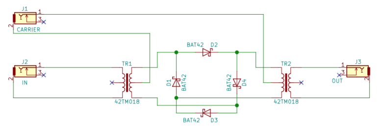
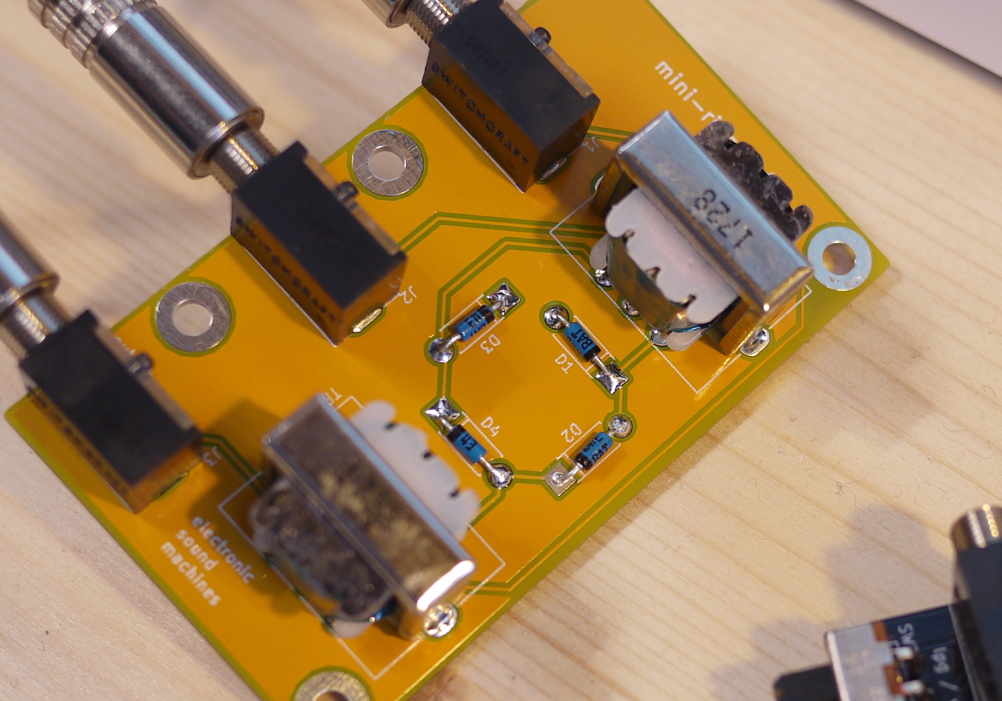
Building the ringmod
It is easier to mount the smallest components first, in this case the diodes.
Measure approximately where the legs needs to be bent, bend the legs smoothly in a 90 degrees angle, and put the component through the correct holes of the circuit board. Diodes must be placed in a certain direction: the ring on the edge of a diode should be where there is a line on the component layout print (the line on the circuit board is very close to one of the pads). The component should be on the top side of the circuit board, with component outlines printed on it.
After putting the diode against the board, with legs through holes, bend the legs slightly outwards (or inwards), just enough to keep the component in place when turning the board upside down. When all diodes are mounted, turn the board upside down and solder the diodes in place. Cut the legs right above the solder joint when done.
Next, mount the jacks. After putting them in place, you might want to bend the lugs slightly outwards. Then turn the board upside down, with the jacks in place. Find something of appropriate height to prop the board up at the back (I found that the transformers were ok for that), so that the jacks stay reasonably parallell to the board. Solder the rear jack first, and then check that the jacks are aligned OK (if they are not straight, it is still possible to heat the rear solder joint and adjust the jack, if you like it neat; it is not important for the function of the jack). Solder the rest of the lugs.
Next up – the final step – are the two transformers. Carefully straighten the legs, make sure that the ”P” is facing the edges of the PCB (not super important for these particular transformers, since the number of windings are equal on both sides, but it gives a good feeling inside to know that everything is in order, yeah?), and put the legs and the two metal tabs through the holes. As before, turn the PCB upside down and prop it up against something (or ask a friend to hold it in position), and solder one leg on each transformer. Check that they are properly aligned and flush against the board before continuing.
After soldering all pins on both transformers, it’s time to test it. If all is well, bend the metal tabs inwards to better hold the transformer in place. For an even more sturdy construction, solder the tabs as well.