minidrum
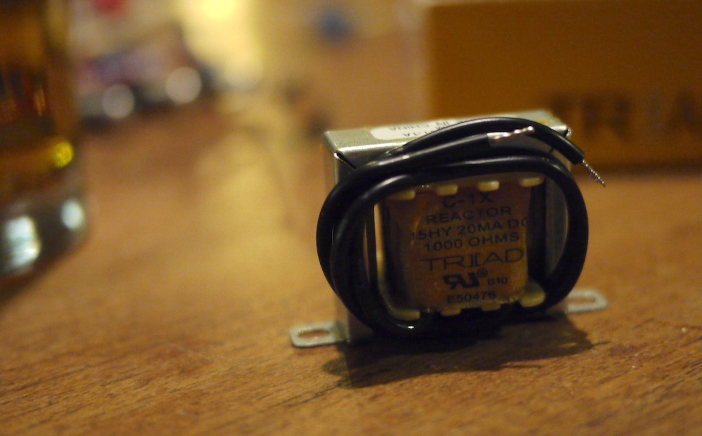
This is an attempt to re-create a lot of the old Roland rhythm machine sounds on one PCB (this endeavour could also be categorized under “needs more focus”). Many old rhythm machines, e.g. the CR-78 and the TR-77, use a similar basic circuit – a chain of resistors and capacitors together with one coil – to create sounds like rim shot, claves, toms, and on TR-77 even the bass drum. One big difference between the sounds is the coil’s inductance – the other component values as well, of course, as they are chosen to match to coil’s inductance.
My understanding (which is very rudimentary and with a bit of guessing) of the circuit is that it basically is a band pass filter: at its core, there’s a coil and one or two capacitors in parallell to it that have a resonant frequency – at that frequency the parallell impedance is at its peak.
I was (and am) really excited about the fact that these sounds were created using passive electronics, that the sound in fact is just the trigger pulse being filtered, basically. When plugging it in, though, it became apparent that the sound was very weak, it kind of needed the active circuitry that was somewhere before and after the circuit in the original machine. On my bass drum implementation, I added a dual OP amp to boost and buffer.
The switches
The PCB has switches for all places where the sounds differ in component types, and also means to connect an extra internal coil (and also an external). The idea was that you could build one basic sound (e.g. rim shot), and then add another coil and other components that could build another sound (e.g. claves), and that the switches could be used to switch – entirely or partly – between those sounds.
So in theory it is possible to have two of those old sounds in one module; in practice it became obvious that more time should have been spent on experimenting before ordering and building the PCB – many of the switches seem pretty useless (in my configuration), and there are also some non-switchable components that could benefit from a switch (e.g. for the bass drum; since it uses such a big coil, and operates on such low frequencies, many other components like capacitors are chosen to match, and when switching to a much smaller coil, one would also like to switch those capacitors to smaller values). Also, even the brighter sounds (like claves) have pretty big inductance coils, and there is no room for such a big secondary coil on the PCB – you’d have to mount it somewhere else.
The jacks
One jack for the input gate signal, one jack for the sound output – pretty basic so far. Note that since the sound is the input gate being filtered, varying the gate’s amplitude should result in varying output amplitudes.
Then there is one additional jack. Originally meant for making it possible to add an external coil (I have experimented a bit with coils from relays etc., and figured it’d be nice with a quick way to jack them into this circuit), but it is also possible to use it as an output – taking the output directly from the coil/capacitor resonant sub-circuit, skipping the rest – which is what I did before I added an OP amp for amplification (the sound level was higher at that point in the circuit).
The potentiometer
The bass drum circuit in TR-77 has a low pass filter on the output, I figured I’d make that adjustable. Not super useful, as it turned out.
The sound
There is a little demo of it here.
Oddities
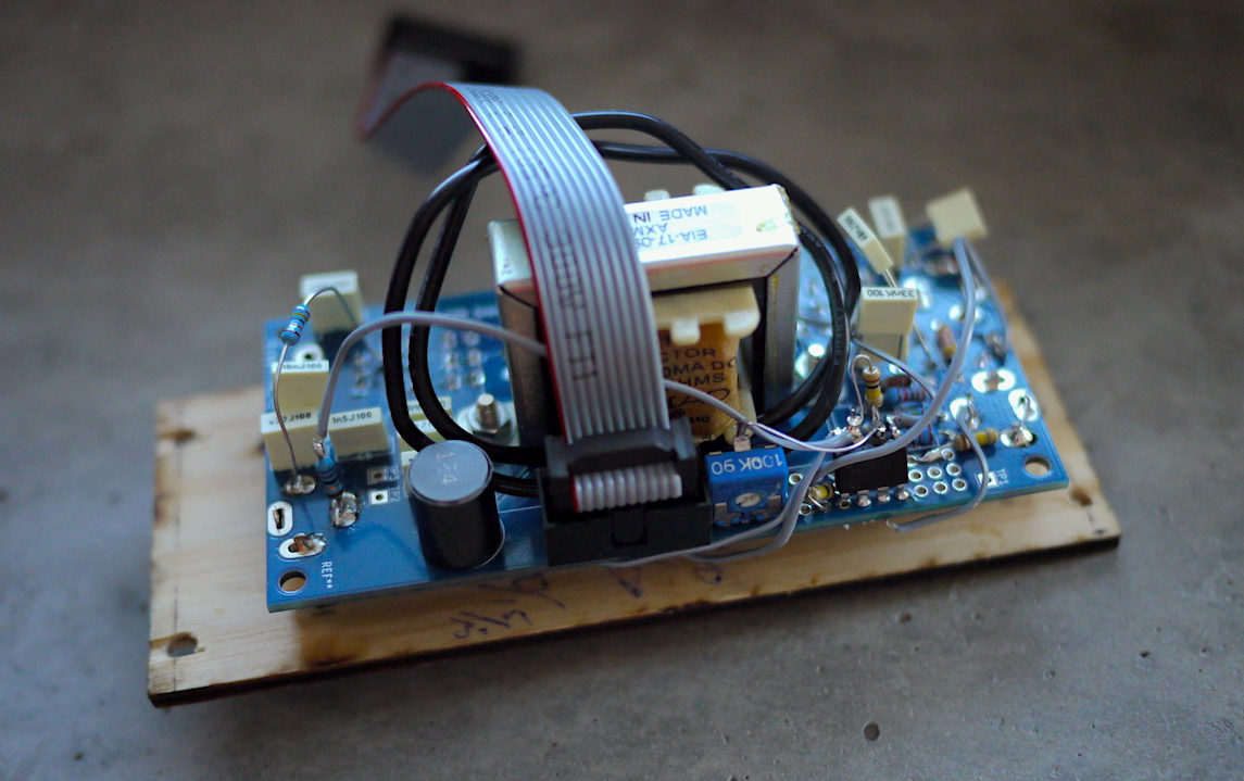
The intention was to make a PCB that allows for experimentation, hence all the switches and also the inclusion of a “mod area” – a part of the PCB with a lot of holes to mount any modifications. Unfortunately, there could have been a little more thinking, and experimentation, before ordering the PCB; instead it’s equipped with the following oddities:
- The passive filter circuit creates a way to soft sound, at least the bass drum sound (which is the only one implemented so far). To remedy that, I reluctantly added a dual OP amp IC in the mod area on my first (and so far only) build; one stage to amplify and buffer the incoming gate pulse (amplified two times, so that a 5V puls almost hits the 12V rail – since many of my gates are 5V that gives an almost maximum output), and one stage to amplify the output (I put a trim pot there, which I tweaked until the kick drum sound was as loud as it could be).
- Modding the PCB as described above made it clear that the mod area is way too small – I had to put the IC with four legs in the air.
- There are loads of switches to switch between sound configurations, but – at least when building the kick drum – there are a few capacitors that are not switchable, that really would need to be, when having one coil of 15 H, and a secondary coil at 120 mH.
- Similarly, a lot of the switches that are in place either doesn’t change that much, or changes too much (e.g. to almost silence). This could probably be at least partly fixed by selecting the secondary components with greater care, but I haven’t had the time nor the energy to do that.
- One of the pads for R1 is located under the big coil’s mounting frame – had to solder that first.
- The potentiometer R5 is “the wrong way”, it gets brighter when turning it counterclockwise.
- Those coils are quite expensive, so even though it is a simple circuit with few components, it does get a bit expensive.
Conclusion
Should you build one? Do I regret building one? Well, it is a bit expensive, given how little it does, but I kind of like having a bass drum sound I don’t have to tweak (or can’t tweak, for that matter). I have PCBs and more coils, if you’re up for it. :-)
My biggest regret is that it takes up so much rack space, not that it cost more than I’d like. Oh, and all those useless switches. If you do build one, consider either keeping it simple, or taking your time experimenting. In other words: If you only build a bass drum, maybe just add the bare minimum, not switches and extra capacitors etc. – that will cut the cost a bit, since coils and hardware like switches/jacks/pots are what’s most expensive here. Or do the other extreme – experiment with component values more carefully than I did, to maybe find a useful combination, and get some use from all those switches.